The snow load generator can generate snow loads as member loads or surface loads.
Additional snow loads such as drifted snow loads, snow overhangs, and snow guards can be taken into account as well.
The following standards are available:
-
 EN 1991-1-3 (incl. National Annexes)
 -
 DIN 1055-5
 -
 CTE DB-SE-AE
 -
 ASCE/SEI 7-16

Wind loads can be automatically generated as member loads or area loads on the following structural components (optional with internal pressure for open buildings):
- Vertical walls
- Flat roofs
- Monopitch roofs
- Duopitch/troughed roofs
- Vertical walls with roof
The following standards are available:
-
EN 1991-1-3 (incl. National Annexes)
-
DIN 1055-4
-
CTE DB-SE-AE
-
ASCE/SEI 7-16
Area loads can be automatically converted into member or line loads. There are 3 options available for this:
- Generate Member Loads from Area Load via Plane
- Member loads from area loads via cells
- Line loads from surface loads on openings
In the case of member loads from area loads, a plane has to be defined via corner nodes or cells have to be selected in the graphic. The area load can either be applied to the entire surface or only the effective or projected surface of the members.
For the 'Line Loads from Area Loads on Openings' function, the corresponding openings are selected.
Online Manual RFEM | Member Loads from Area Loads via Plane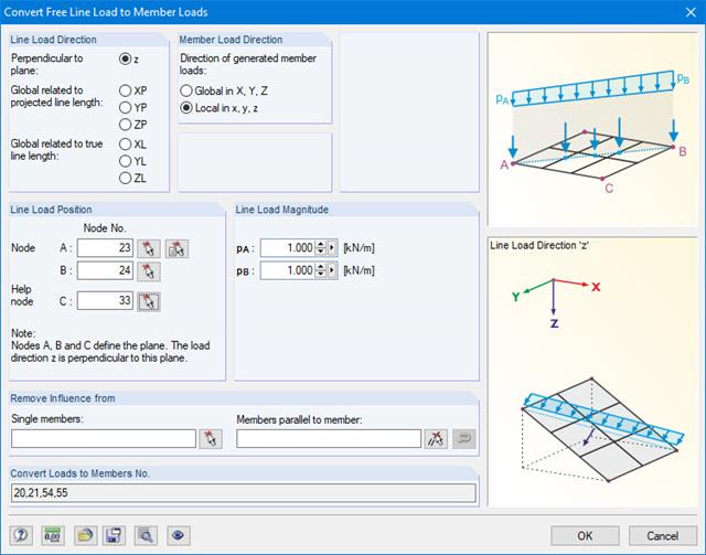
For pure member models such as grillages, you can define free line loads (e.g. from conveyor belts) and transfer them proportionally to members.
More Information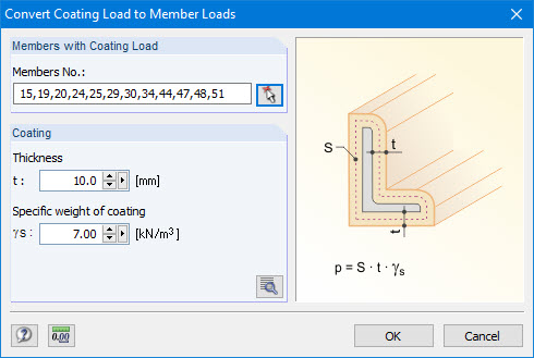
Coating loads can be generated as member loads from ice loads, claddings, and so on.
For this, you only have to specify the thickness and specific weight of the coating.
Manual RFEM 5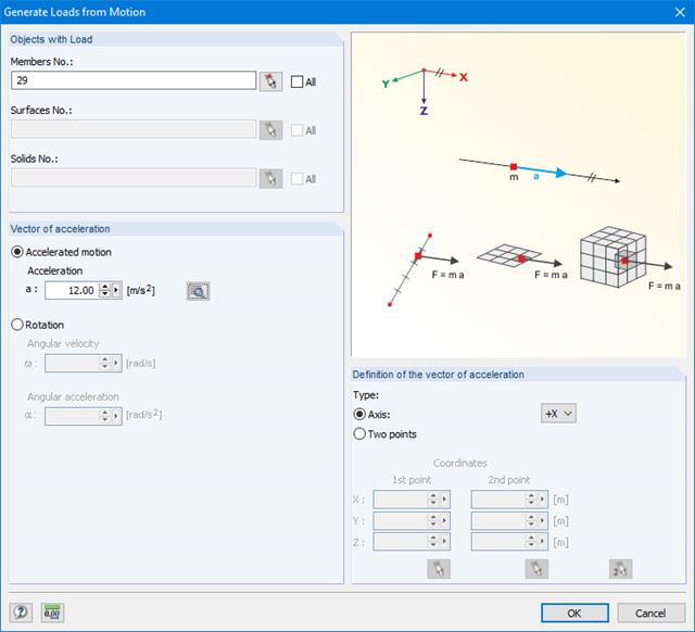
This generator creates loads as a result of an acceleration or rotation (e.g. from tower cranes), which acts on specific objects of the model.
The mass is determined from the self-weight.
More Information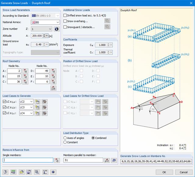
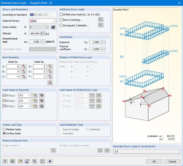
Snow loads can be generated as member loads on flat/monopitch roofs and duopitch roofs.
Additional snow loads such as drifted snow loads, snow overhangs, and snow guards can be taken into account as well.
The following standards are available:
-
EN 1991-1-3 (incl. National Annexes)
-
DIN 1055-5
-
CTE DB-SE-AE
-
ASCE/SEI 7-16
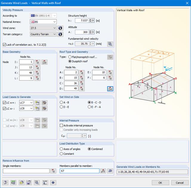
Wind loads can be automatically generated as member loads on the following structural components (optional with internal pressure for open buildings):
- Vertical walls
- Flat roofs
- Monopitch roofs
- Duopitch/troughed roofs
- Vertical walls with roof
The following standards are available:
-
EN 1991-1-3 (incl. National Annexes)
-
DIN 1055-4
-
CTE DB-SE-AE
-
ASCE/SEI 7-16
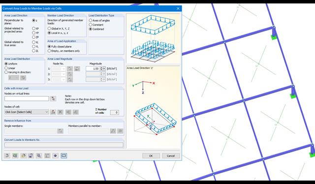
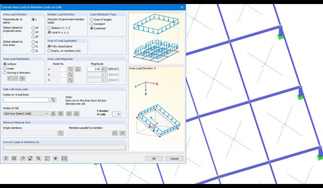
Area loads can be automatically converted into member loads. There are 2 options available for this:
- Generate Member Loads from Area Load via Plane
- Member loads from area loads via cells
Depending on the selected option, you either have to define a plane via corner nodes or select cells in the graphic. The area load can either be applied to the entire surface or only the effective or projected surface of the members.
Online Manual RFEM | Member Loads from Area Loads via Plane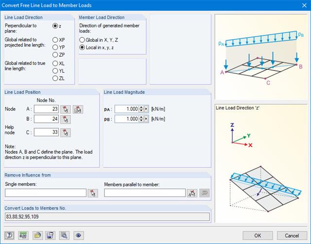
With this generator, you can e.g. for grillages, you can define free line loads (e.g. from conveyor belts) and prorate them to members.
More Information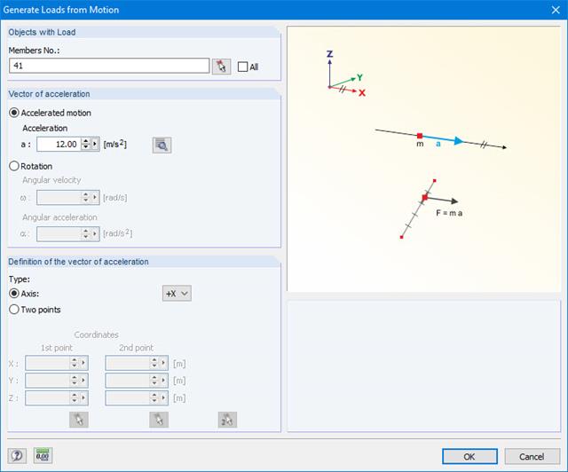
This generator creates loads as a result of an acceleration or rotation that acts on specific objects of the model.
The mass is determined from the self-weight.
More Information
The material library already includes Swiss types of concrete and reinforcing steel available for design. However, you can always define other materials for the design according to SIA 262. The program performs the ultimate and the serviceability limit state design.
The crack width analysis can be performed using the design of Sigmas,adm, rebar spacing sL, or a direct calculation of crack widths according to the technical documentation D0182. Depending on the selected concrete type, the program determines the limit value Sigmas,adm according to D0182, Eq. 10.13; the upper limit is set by the design criterion fsd.
The material library already includes the Chinese types of concrete and reinforcing steel available for design. However, you can always define other materials for the design according to GB 50010.
In addition, it is possible consider the seismic design according to the standard GB 50011‑2010 (Code for seismic design of buildings).
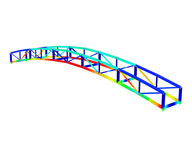
- Design of tension, compression, bending, shear, combined internal forces, and torsion
- Stability analysis for flexural buckling, torsional buckling, and lateral-torsional buckling
- Optional application of discrete lateral supports to beams
- Deformation analysis (serviceability)
- Cross-section optimization
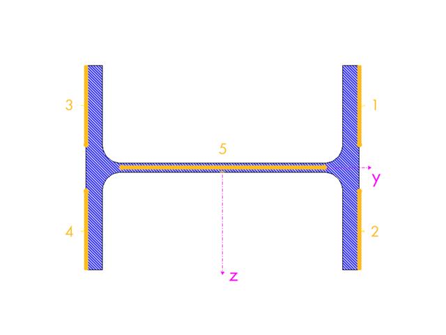
- Wide range of cross-sections available, such as rolled I-sections, channel sections, rectangular hollow sections, angles, T-sections. Welded sections: I-shaped (symmetrical and asymmetrical about major axis), channel sections (symmetrical about major axis), rectangular hollow sections (symmetrical and asymmetrical about major axis), angles, round pipes, and round bars
- Clearly arranged result tables
- Detailed result documentation including references to design equations of the used standard
- Various filter and sorting options of results, including result lists by member, cross-sections, x-location, or by load case, load and result combination
- Result table of member slenderness and governing internal forces
- Parts list with weight and solid specifications
- Seamless integration in RFEM/RSTAB
.png?mw=640&hash=721e09a7520480378145fa75eaabf5a5bed8f7e3)
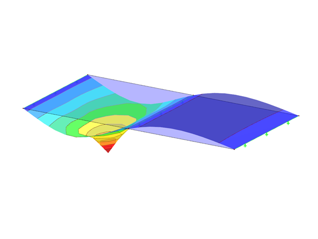
- Full integration in RFEM/RSTAB including import of all relevant information and internal forces
- Determination of stress ranges for the available load cases and load or result combinations
- Free assignment of detail categories on the available stress points of the cross-section
- User-defined specification of damage equivalent factors
- Design of members and sets of members according to EN 1993-1-9
- Optimization of cross-sections with the option to transfer the data to RFEM/RSTAB
- Detailed result documentation with references to design equations used
- Various filter and sorting options of results, including result lists by member, cross-sections, x-location, or by load case, load and result combination
- Visualization of the design criterion on RFEM/RSTAB model
- Data export to MS Excel
- Full integration in RFEM/RSTAB with import of relevant internal forces
- Design checks for the elastic-elastic and elastic-plastic methods
- Graphical selection of members and sets of members for design
- Analysis for several load and design cases
- Design based on the buckling field parameters integrated in the cross-section library for the cross-section parts supported on one and both sides
- Optional determination of shear stresses according to comment on El. (745)
- Possibility to consider the weld thickness in the design of welded cross-sections, which has the effect of a shortening of the cross-section part width
- Cross-section optimization with the option to export modified cross-sections
- Simple definition of unit loads in RFEM model
- Simple definition of the points on members, surfaces, and supports to be analyzed
- Numerical results and graphical display of unit load or designed point results
- Detailed printout report, including all model and load data of each designed point and unit load used
.png?mw=640&hash=34966a7f3c34f6b7bb83003f1c13cb57a2f0cabb)
- Realistic representation of interaction between a building and soil
- Extensible library of soil properties
- Consideration of several soil samples (probes) at different locations, even outside the building
- Consideration of groundwater level as well as side effects due to excavation and lowest soil layer being solid
- Calculation of elastic foundation coefficients
- Determination and graphical display of stress diagrams and settlements in grid points
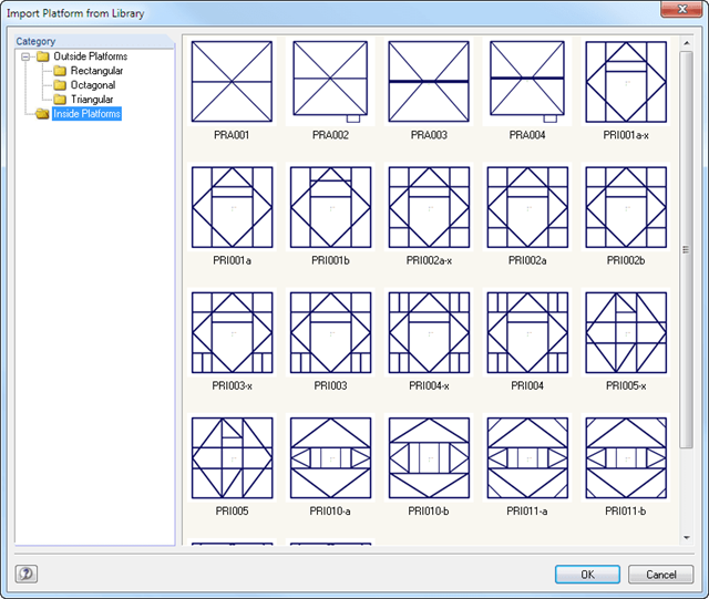
You can define platforms, tubular extensions, antenna brackets, antennas, inner ducts, cable ducts, and ladders in separate input windows. Extensive libraries including parameterized models facilitate the entry.
There is an interactive graphic available in all input windows. This way, you can immediately see the position of tower equipment.
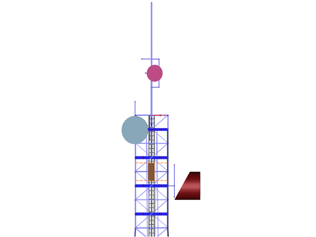
- Generation of inside and outside platforms using the library, including parameterized models
- Tubular extension and antenna bracket libraries as 2D and 3D structures
- Antenna groups sorted by mobile network operator
- Antenna library including parabolic, lense, shell, compact, and cuboidal antennas
- Parameterized input of inner and cable ducts as well as ladders with interactive graphics